- Name: FSANS –Time of Flight Small Angle Neutron Scattering instrument
- Technique: time of flight based small angle neutron scattering
- Range of investigated features: 2.5 to 600 nm
- Penetration depth: several millimetres
- Typical size of sample: from few mm to few cm, with several mm in thickness
- Measurable materials: liquids and solids
- Contact: fsans@bnc.hu
- Poster of the instrument
The FSANS instrument is a time-of-flight type diffractometer, covering a momentum transfer or Q-range from 0.001 to 0.266 Å-1, enabling the study of structures at corresponding length scales ranging from 2.5 to 600 nm.
The SANS method, and consequently the FSANS instrument, have a wide range of applications, encompassing the study of defects and precipitates in materials, alloy segregations, nanostructures of surfactant and colloid solutions, polymers, proteins, characteristics of biological membranes, ferromagnetics, magnetic correlations, and more.
The instrument is situated on the lower segment of the curved neutron guide No.10/3, constructed with m = 2 supermirrors. It operates with a beam time structure defined by three choppers: a counter-rotating pair of pulse definition choppers, and a wavelength limiting and frame overlap chopper. The available wavelength range spans from 2 to 14 Å. The width of wavelength uncertainty, Δλ, can be set by selecting the pulse definition chopper window to either 0.3 Å with at 8° opening (better resolution mode) or 0.75 Å with 20° opening (higher intensity mode), respectively. The collimation and maximum sample-to-detector distances are 3.7 and 4.3 m, respectively. The instrument’s configuration is illustrated in Figure 1. The detector allows for both vertical and horizontal movement, as well as bidirectional tilting of the detector arm, providing a high level of flexibility compared to standard settings.
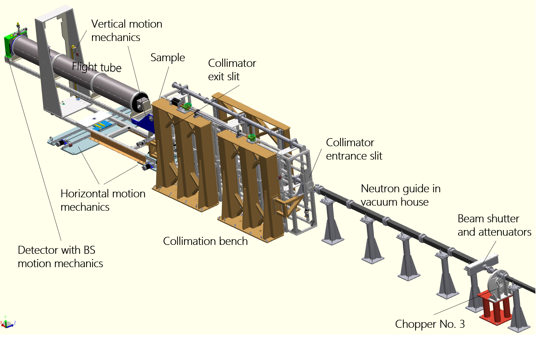
Figure 1. Layout of the FSANS diffractometer
Samples ranging from several millimetres to several tens of centimetres in diameter can be accomodated at the sample position. The beam size is adjustable, ranging from 1 to 27 mm in diameter.
Scattered neutrons are captured by a 256 × 256 pixel two-dimensional position-sensitive detector, with a pixel measuring 0.7×0.7 mm2, filled with 3He-CF4 gas mixture. Data acquisition is carried out in event recording mode. The detector’s vertical and horizontal movement, along with bidirectional tilting of the detector arm, provide a notable degree of flexibility compared to the default settings.
The spectrum measured on the No.10/3 cold neutron beamline of the Budapest Research Reactor (representing the intensity distribution transmitted from the cold source spectrum by the neutron guides) at the location of the FSANS instrument is depicted in Figure 2.
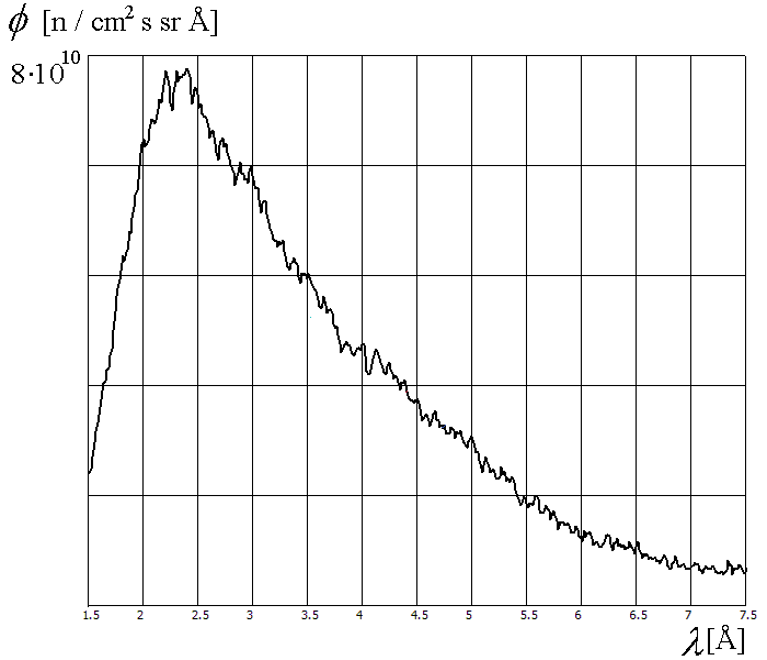
Figure 2. The spectrum measured on the 10/3 cold neutron beamline of the Budapest Research Reactor at the FSANS instrument’s position
The following table presents the key characteristics of the FSANS instrument. Default configuration: the detector is positioned in-line with the direction of the direct neutron beam.
| FSANS characteristics (default configuration) | Details | |
| Beam | Cold neutron guide No. 10/3 | Cross section of the neutron guide at the exit: 25 x 25 mm2 |
| Monochromation | Chopper system with three choppers | 1st and 2nd Choppers: counter-rotating pair of pulse definition choppers. Openings: 8°@0°and 20°@90°. Maximum rotation speed: 3000 rot/min. Disc diameter: 400 mm. 3rd Chopper: wavelength limiting and frame overlap chopper. Openings: 42°@0°and 42°@180°. Maximum rotation speed: 1500 rot/min. Disc diameter: 400 mm. |
| Detector | 2D position sensitive | Type: 3He-CF4 gas detector Size: 200×200 mm2 Pixel size: 0.7×0.7 mm2 Beam-stop diameters: 4, 8, 10, 14, 20 mm, with x, y motion. |
| Collimation length | 3.7 m | The future option for adjusting collimation and focusing mirror installation is permitted. Various slit sizes at both ends of the collimator are available with automatic motion control. Slit diameters at the sample size: 1, 10, 20, 27 mm and a rectangular slit: 3 mm x 19 mm. |
| Sample to detector distance | 1 to 4.3 m Vacuumed flight path between sample and detector | Detector arm with automatic motion control: – front end horizontal translation: ± 100 mm; – front end vertical translation: ± 200 mm; – back end horizontal translation: ± 700 mm; – back end vertical rotation: – 7° … + 10°. Flight tube: – length: 3500 mm, composed of 4 detachable sections; – inner diameter: 280 mm; – inner diameter at the inlet side: 70 mm. |
| Wavelength range | 2 – 14 Å | The maximum of the Maxwell-Boltzmann spectra is between 2 and 3 Å. Wavelength uncertainty: 0.3 – 0.74 Å |
| Scattering vector range | 0.0006 – 0.2663 Å-1 | Scattering vector resolution: 0.00005 Å-1 |
| Sample environment | Multipurpose sample changer under development | |
Figure 3 displays an example of a small angle scattering measurement. Data were collected using both the FSANS and the SANS-YS instruments. The samples under study were multi-wall carbon nanotubes/epoxy polymer composites. The SANS measurements facilitated the characterization of the nanostructure of the various composites at a broad length-scale, which was subsequently correlated with their electrical conductivity properties [1].
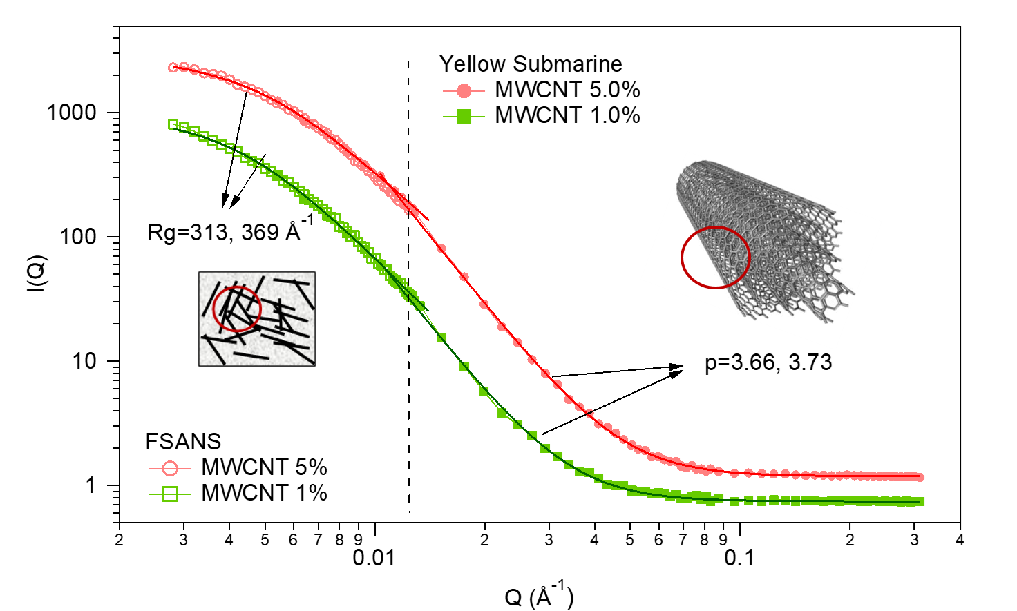
Figure 3. SANS measurements on CNT/epoxy composites conducted with the FSANS and YS-SANS instruments
In addition to its general application in small angle neutron scattering, the FSANS instrument has been retailored to facilitate non-destructive archaeological investigations. When SANS is applied to ceramics, the resulting scattering pattern can provide valuable insights into the average orientation and degree of elongation (anisotropy) of nano-sized particles (Figure 4) such as clay minerals and pores. These characteristics are closely linked to the forces experienced during the vessel forming process (Figure 5a). Thus, by analysing the orientation, it becomes possible to infer the forming technique used to produce the vessel, in a non-destructive way (Figure 5, b and c). This information to deduce the forming technique used to create the vessel, in a non-destructive way. This information proves particularly beneficial in cases where the vessel’s macro-structural features, indicative of the primary forming technique, are obscured by secondary techniques like polishing, burnishing, smoothing, painting, glazing, or by environmental impacts like soil erosion. Furthermore, SANS enables non-destructive differentiation between techniques that may exhibit similar macroscopic characteristics, such as wheel-throwing and wheel-shaping [2, 3].
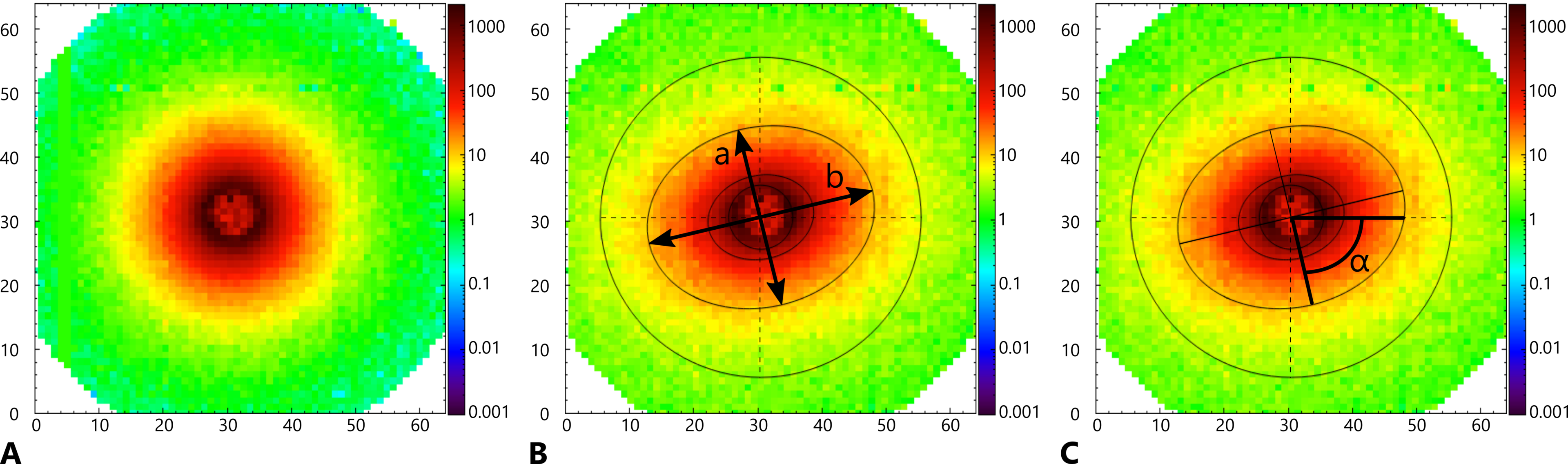
Figure 4. SANS 2D neutron scattering intensity distribution diagrams. A Isotropic scattering; B anisotropic neutron scattering, with the ‘isotropy’ of the interfaces of the scattering domains, I, calculated as the ratio of the lengths of the minor and major axes of the fitted ellipse (I = a/b where a ≤ b, 0 < I ≤ 1); C mean tilting angle, α, of interfaces of scattering domains measured as the angle from the positive horizontal axis to the nearest minor axis of the ellipse fitted to the neutron scattering intensity distribution (-90° < α ≤ 90°)
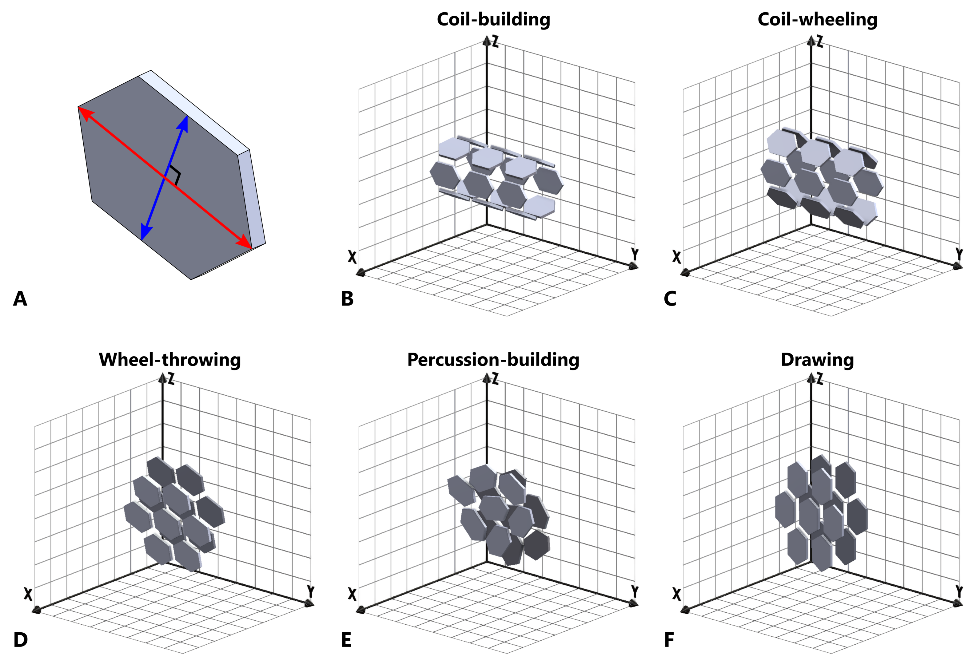
Figure 5. Schematic models (not to scale) showing the simplified 3D orientations of hypothetical particles resulting from different forming techniques. A Hypothetical rigid, tri-axial particle, showing primary and secondary axes as red and blue arrows respectively; B coil-section/coil-building; C coil-wheeled; D wheel-thrown (anticlockwise wheel rotation); E percussion-building/percussion-wheeling; F drawing/drawing-wheeled
References:
[1] Boukheir, S ; Len, A ; Fuzi, J ; Kenderesi, V ; Achour, ME; Eber, N ; Costa, LC ; Oueriagli, A ; Outzourhit, A; Fractal structure and temperature-dependent electrical study of carbon nanotubes/epoxy polymer composites; SPECTROSCOPY LETTERS 50 : 4 pp. 183-188. , 6 p. (2017)
[2] Len, A. ; Bajnok, K.; Füzi, J.: Small-Angle Neutron Scattering for Cultural Heritage Studies; In: D’Amico, S; Venuti, V (szerk.) Handbook of Cultural Heritage Analysis; Cham, Svájc : Springer-Verlag (2022) 2,256 p. pp. 189-210. , 22 p.
[3] Gait, J.; Bajnok, K.; Hugot, N.; Horváth, F.; Pépy, G.; Ellis, D.; Len, A.: Novel application of SANS provides quantitative non-destructive identification of forming techniques in late Roman and early medieval pottery from Pannonia, SCIENTIFIC REPORTS 14 : 1 Paper: 25926 , 26 p. (2024)